logo
Products
PRODUCTS DETAILS
Home > Products >
HFBR-4501 to HFBR-4511 POF Cable Assembly

HFBR-4501 to HFBR-4511 POF Cable Assembly

MOQ: 100
Price: USD 0.5–3.2/Piece
Delivery Period: 5-8 work days
Payment Method: L/C,D/A,D/P
Detail Information
Product Format:
Passive, Pre-terminated POF Cable Assembly
Optical Channels:
One Channel Per Simplex Assembly
Optical Fiber:
1.0±0.04 Mm Step-index PMMA POF
Standard Jacket:
Black PE
Standard Cable Diameter:
2.2±0.1 Mm
Connector A:
Gray HFBR-4501-style Simplex Crimp Connector
Connector B:
Blue HFBR-4511-style Simplex Crimp Connector
Termination Structure:
Metal/aluminum Crimp Rings With Finished Fiber End Faces
Drawing Test Wavelength:
650 Nm LED
Standard Lengths:
1 M, 2 M And 3 M
Standard Assembly Loss:
≤2.0 DB At 1 M; ≤2.4 DB At 2 M; ≤2.8 DB At 3 M
Length Tolerance:
±10 Mm At 1 M; ±15 Mm At 2 M And 3 M
Strain-relief Option:
Basic Version Or Dual 40 Mm Black Boots
End-face Protection:
Black Dust Caps
Connector-body Requirement:
ABS AF312C With Component-level V-0 Material Requirement
Project Options:
Custom Length, Jacket, Diameter, Reinforcement, Temperature, Flame, Halogen-free, Testing, Labeling And Packaging Requirements
Product Description

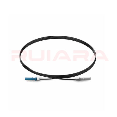
Our HFBR-4501 to HFBR-4511 POF Cable Assembly is a passive, pre-terminated 1.0 mm PMMA plastic optical fiber cable for industrial equipment using the Versatile Link simplex connector format. Each assembly provides one optical channel through a black single-core cable, with a gray HFBR-4501-style connector at one end and a blue HFBR-4511-style connector at the other.

We manufacture the complete assembly—from cable jacketing and cut-to-length processing through crimp termination, end-face finishing, optical testing and final assembly. Standard 1 m, 2 m and 3 m versions are available, together with booted constructions and project-specific cable configurations.

  • Single-channel 1.0 mm step-index PMMA POF
  • Standard black PE jacket with 2.2±0.1 mm outer diameter
  • Complete-assembly loss limits defined for standard 1 m, 2 m and 3 m models
  • Optional boots, dust caps, jacket constructions and project labeling
  • OEM production with drawing control, sample approval and traceable inspection

Standard Model Selection
Model Finished Length Complete-Assembly Loss Limit
QH221-010 1000±10 mm ≤2.0 dB
QH221-020 2000±15 mm ≤2.4 dB
QH221-030 3000±15 mm ≤2.8 dB

The listed loss values are drawing limits for the complete connectorized assembly under a 650 nm LED test condition. They are not bare-fiber attenuation or cable attenuation per metre.

A booted 1 m construction is also available with two 40 mm black boots, two dust caps and plated aluminum crimp rings. Because the booted version uses its own drawing and length tolerance, its optical acceptance criteria are finalized in the approved project specification.

HFBR-4501 and HFBR-4511 Simplex Interface Configuration

The gray and blue connectors are mechanically based on the same simplex crimp interface. Their colors help identify the optical direction commonly used in Versatile Link systems:

  • Gray HFBR-4501 end: normally connected to the transmitter side
  • Blue HFBR-4511 end: normally connected to the receiver side
  • One gray-to-blue cable assembly: one optical transmission channel
  • Full-duplex communication: normally requires two simplex optical channels

The color convention does not make the fiber itself directional. Always verify the transmitter and receiver positions in the equipment manual, especially when replacing an existing cable or working with equipment that uses a special port arrangement.

Special end combinations, including same-color connectors, can be developed when the equipment topology and port roles are clearly defined.

Related Connector Configurations
Connector Family Configuration Typical Selection Reason
HFBR-4501 / 4511 Standard simplex crimp Target configuration on this page
HFBR-4503 / 4513 Latching simplex crimp Higher retention or equipment requiring a locking connector
HFBR-4506 / 4516 Duplex crimp Two-channel duplex interface
HFBR-4531 / 4532 / 4533 / 4535 Crimpless simplex types Alternative field or assembly configuration
HFBR-4505 / 4515 Simplex mating adapter Bulkhead, feedthrough or inline connection

Our finished cable assembly is manufactured by us. The HFBR model references identify the connector format and application ecosystem; they do not identify the complete assembly as a Broadcom, Avago or Mitsubishi original cable product.

For equipment matching, confirm:

  • Connector model and locking style
  • Gray Tx and blue Rx port positions
  • 1.0 mm POF requirement
  • Number of simplex channels
  • Required finished length
  • Available installation space and bend path
  • Permitted link loss and system distance
  • Temperature, flame and environmental requirements

Equipment photographs, port part numbers, drawings or an existing sample can be used for configuration verification.

Manufactured as a Complete Industrial POF Assembly

The product is supplied as a finished, tested cable assembly rather than as loose fiber, bulk cable or connector components. Our manufacturing control covers the stages that directly affect mechanical fit, optical coupling and production consistency.

Assembly Process
  1. Jacket and cable-structure processing for the specified 1.0 mm POF construction
  2. Cut-to-length preparation and controlled jacket stripping
  3. Gray and blue connector positioning and metal-ring crimping
  4. Fiber trimming, end-face finishing and polishing
  5. Installation of boots, dust caps and project accessories
  6. Visual, dimensional, end-face and optical inspection
  7. Final labeling, packaging and production-record control

A properly finished POF end face should be flat, smooth and clean. Scratches, contamination, poor fiber positioning or uncontrolled crimping can increase coupling loss even when the connector can still be inserted into the equipment port.

Production and Project Quality Control

Inspection plans can include:

  • Cable diameter, finished length and connector-orientation checks
  • Crimp position and assembly-appearance inspection
  • End-face cleanliness and finishing inspection
  • Complete-assembly optical loss testing
  • Connector retention and cable-to-connector tensile verification
  • Flex, torsion, strain-relief or environmental testing when required
  • Batch, drawing-revision, test-equipment and operator traceability

For OEM projects, the normal workflow can include requirement review, prototype production, sample approval, first-article inspection, drawing and revision control, production inspection and delivery of agreed test or traceability records.

Configurable Cable Construction for Industrial Projects

The standard product uses a black 2.2 mm PE-jacketed cable. For applications with different routing, mechanical or environmental conditions, we can develop and validate alternative constructions.

Project Requirement Available Direction Confirmation Required
Finished length Custom cut length beyond standard 1 m, 2 m and 3 m models Length tolerance and optical acceptance
Jacket material PE, PVC, PA/Nylon, PUR, CPE or XLPE-based direction Temperature, chemical and compliance requirements
Cable structure Single jacket, dual jacket or reinforced construction Connector transition and crimp compatibility
Cable diameter Standard 2.2 mm or project-specific outer diameter Termination structure and pull performance
Installation environment Indoor, outdoor, equipment cabinet or moving installation UV, moisture, flex and routing conditions
Strain relief Without long boot or with project-specific boots Boot length and available installation space
End configuration Gray-to-blue standard or special connector combination Equipment port roles and approved drawing
Compliance direction Flame-retardant, halogen-free, RoHS or REACH support Approved BOM and applicable documentation
Testing Optical, retention, tensile, flex, vibration, shock or temperature cycling Test method, sample size and acceptance limits
Identification and packing Barcode, serial number, customer label, color sleeve, individual bag or kitting Customer format and packing specification

Larger or reinforced cables require a validated transition between the cable body and the HFBR connector termination. A similar outside appearance alone does not confirm crimp compatibility, retention strength or optical performance.

Temperature and flame requirements are also construction-specific. Connector-material ratings, jacket flame tests and fiber temperature limits apply to different objects and cannot be combined into an unverified rating for the complete assembly. For elevated-temperature projects, the full fiber, jacket, connector, crimp and strain-relief construction should be selected and validated together.

Optical Performance, Installation and Link Planning

Three different optical values should be kept separate when selecting an industrial POF assembly:

  • Complete-assembly loss: Includes the terminated cable and both finished connector ends. The standard model limits are listed above.
  • Cable attenuation: Measured separately over a defined cable length and recorded in dB/m under a specified wavelength and reference method.
  • System reach: Determined by the transmitter output, receiver sensitivity, cable attenuation, connector and adapter losses, temperature, data rate and required optical margin.

A cable that can be manufactured at a particular length does not automatically guarantee communication over that distance. The final usable length must be checked against the selected transmitter, receiver and system link budget.

For installation of the standard HFBR jump cable:

  • Maintain a bend radius of at least 22 mm, or use the larger radius required by the equipment specification.
  • Keep short-term installation tension at or below 50 N.
  • Keep continuous tension at or below 1 N.
  • Pull and disconnect the connector body rather than the cable.
  • Protect polished end faces from dust, oil and scratches.
  • Keep unused connectors covered with dust caps.
  • Avoid tight knots, repeated twisting and forced uncoiling.
  • Confirm the effect of solvents, adhesives, oils, plasticizers or other chemicals before exposure.

When adapters are introduced, their coupling loss must also be included in the link budget. A mating adapter and two simplex connectors form a separate connection point and should not be treated as part of the cable’s per-metre attenuation.

Industrial Power, Automation and Control Applications

The non-conductive POF transmission path makes this cable assembly suitable for short-distance optical communication where electrical isolation and resistance to electromagnetic interference are important.

Typical applications include:

  • Substation protection and control communication
  • Industrial fieldbus and factory-automation links
  • Power-electronics control and feedback
  • High-voltage galvanic-isolation links
  • Frequency converters, inverters and motor-control equipment
  • IGBT, GTO and related gate-control systems
  • Board-to-board and rack-to-rack optical connections
  • Industrial instruments, controllers, sensors and protection relays

The HFBR-4501/4511 interface family is documented in industrial equipment such as ABB REF542plus protection and control units and ABB SPACOM/SPA systems. These references demonstrate established use of the connector ecosystem in power applications, but the exact connector configuration, permitted length and optical budget must still be checked for each device.

The cable assembly transports the optical signal; it does not perform electrical-to-optical or optical-to-electrical conversion. A complete link requires the appropriate transmitter and receiver modules.

Send us your required length, equipment port details, quantity and environmental specifications, and we will prepare the matching drawing, sample and quotation.

Products
PRODUCTS DETAILS
HFBR-4501 to HFBR-4511 POF Cable Assembly
MOQ: 100
Price: USD 0.5–3.2/Piece
Delivery Period: 5-8 work days
Payment Method: L/C,D/A,D/P
Detail Information
Product Format:
Passive, Pre-terminated POF Cable Assembly
Optical Channels:
One Channel Per Simplex Assembly
Optical Fiber:
1.0±0.04 Mm Step-index PMMA POF
Standard Jacket:
Black PE
Standard Cable Diameter:
2.2±0.1 Mm
Connector A:
Gray HFBR-4501-style Simplex Crimp Connector
Connector B:
Blue HFBR-4511-style Simplex Crimp Connector
Termination Structure:
Metal/aluminum Crimp Rings With Finished Fiber End Faces
Drawing Test Wavelength:
650 Nm LED
Standard Lengths:
1 M, 2 M And 3 M
Standard Assembly Loss:
≤2.0 DB At 1 M; ≤2.4 DB At 2 M; ≤2.8 DB At 3 M
Length Tolerance:
±10 Mm At 1 M; ±15 Mm At 2 M And 3 M
Strain-relief Option:
Basic Version Or Dual 40 Mm Black Boots
End-face Protection:
Black Dust Caps
Connector-body Requirement:
ABS AF312C With Component-level V-0 Material Requirement
Project Options:
Custom Length, Jacket, Diameter, Reinforcement, Temperature, Flame, Halogen-free, Testing, Labeling And Packaging Requirements
Minimum Order Quantity:
100
Price:
USD 0.5–3.2/Piece
Delivery Time:
5-8 work days
Payment Terms:
L/C,D/A,D/P
Product Description

Our HFBR-4501 to HFBR-4511 POF Cable Assembly is a passive, pre-terminated 1.0 mm PMMA plastic optical fiber cable for industrial equipment using the Versatile Link simplex connector format. Each assembly provides one optical channel through a black single-core cable, with a gray HFBR-4501-style connector at one end and a blue HFBR-4511-style connector at the other.

We manufacture the complete assembly—from cable jacketing and cut-to-length processing through crimp termination, end-face finishing, optical testing and final assembly. Standard 1 m, 2 m and 3 m versions are available, together with booted constructions and project-specific cable configurations.

  • Single-channel 1.0 mm step-index PMMA POF
  • Standard black PE jacket with 2.2±0.1 mm outer diameter
  • Complete-assembly loss limits defined for standard 1 m, 2 m and 3 m models
  • Optional boots, dust caps, jacket constructions and project labeling
  • OEM production with drawing control, sample approval and traceable inspection

Standard Model Selection
Model Finished Length Complete-Assembly Loss Limit
QH221-010 1000±10 mm ≤2.0 dB
QH221-020 2000±15 mm ≤2.4 dB
QH221-030 3000±15 mm ≤2.8 dB

The listed loss values are drawing limits for the complete connectorized assembly under a 650 nm LED test condition. They are not bare-fiber attenuation or cable attenuation per metre.

A booted 1 m construction is also available with two 40 mm black boots, two dust caps and plated aluminum crimp rings. Because the booted version uses its own drawing and length tolerance, its optical acceptance criteria are finalized in the approved project specification.

HFBR-4501 and HFBR-4511 Simplex Interface Configuration

The gray and blue connectors are mechanically based on the same simplex crimp interface. Their colors help identify the optical direction commonly used in Versatile Link systems:

  • Gray HFBR-4501 end: normally connected to the transmitter side
  • Blue HFBR-4511 end: normally connected to the receiver side
  • One gray-to-blue cable assembly: one optical transmission channel
  • Full-duplex communication: normally requires two simplex optical channels

The color convention does not make the fiber itself directional. Always verify the transmitter and receiver positions in the equipment manual, especially when replacing an existing cable or working with equipment that uses a special port arrangement.

Special end combinations, including same-color connectors, can be developed when the equipment topology and port roles are clearly defined.

Related Connector Configurations
Connector Family Configuration Typical Selection Reason
HFBR-4501 / 4511 Standard simplex crimp Target configuration on this page
HFBR-4503 / 4513 Latching simplex crimp Higher retention or equipment requiring a locking connector
HFBR-4506 / 4516 Duplex crimp Two-channel duplex interface
HFBR-4531 / 4532 / 4533 / 4535 Crimpless simplex types Alternative field or assembly configuration
HFBR-4505 / 4515 Simplex mating adapter Bulkhead, feedthrough or inline connection

Our finished cable assembly is manufactured by us. The HFBR model references identify the connector format and application ecosystem; they do not identify the complete assembly as a Broadcom, Avago or Mitsubishi original cable product.

For equipment matching, confirm:

  • Connector model and locking style
  • Gray Tx and blue Rx port positions
  • 1.0 mm POF requirement
  • Number of simplex channels
  • Required finished length
  • Available installation space and bend path
  • Permitted link loss and system distance
  • Temperature, flame and environmental requirements

Equipment photographs, port part numbers, drawings or an existing sample can be used for configuration verification.

Manufactured as a Complete Industrial POF Assembly

The product is supplied as a finished, tested cable assembly rather than as loose fiber, bulk cable or connector components. Our manufacturing control covers the stages that directly affect mechanical fit, optical coupling and production consistency.

Assembly Process
  1. Jacket and cable-structure processing for the specified 1.0 mm POF construction
  2. Cut-to-length preparation and controlled jacket stripping
  3. Gray and blue connector positioning and metal-ring crimping
  4. Fiber trimming, end-face finishing and polishing
  5. Installation of boots, dust caps and project accessories
  6. Visual, dimensional, end-face and optical inspection
  7. Final labeling, packaging and production-record control

A properly finished POF end face should be flat, smooth and clean. Scratches, contamination, poor fiber positioning or uncontrolled crimping can increase coupling loss even when the connector can still be inserted into the equipment port.

Production and Project Quality Control

Inspection plans can include:

  • Cable diameter, finished length and connector-orientation checks
  • Crimp position and assembly-appearance inspection
  • End-face cleanliness and finishing inspection
  • Complete-assembly optical loss testing
  • Connector retention and cable-to-connector tensile verification
  • Flex, torsion, strain-relief or environmental testing when required
  • Batch, drawing-revision, test-equipment and operator traceability

For OEM projects, the normal workflow can include requirement review, prototype production, sample approval, first-article inspection, drawing and revision control, production inspection and delivery of agreed test or traceability records.

Configurable Cable Construction for Industrial Projects

The standard product uses a black 2.2 mm PE-jacketed cable. For applications with different routing, mechanical or environmental conditions, we can develop and validate alternative constructions.

Project Requirement Available Direction Confirmation Required
Finished length Custom cut length beyond standard 1 m, 2 m and 3 m models Length tolerance and optical acceptance
Jacket material PE, PVC, PA/Nylon, PUR, CPE or XLPE-based direction Temperature, chemical and compliance requirements
Cable structure Single jacket, dual jacket or reinforced construction Connector transition and crimp compatibility
Cable diameter Standard 2.2 mm or project-specific outer diameter Termination structure and pull performance
Installation environment Indoor, outdoor, equipment cabinet or moving installation UV, moisture, flex and routing conditions
Strain relief Without long boot or with project-specific boots Boot length and available installation space
End configuration Gray-to-blue standard or special connector combination Equipment port roles and approved drawing
Compliance direction Flame-retardant, halogen-free, RoHS or REACH support Approved BOM and applicable documentation
Testing Optical, retention, tensile, flex, vibration, shock or temperature cycling Test method, sample size and acceptance limits
Identification and packing Barcode, serial number, customer label, color sleeve, individual bag or kitting Customer format and packing specification

Larger or reinforced cables require a validated transition between the cable body and the HFBR connector termination. A similar outside appearance alone does not confirm crimp compatibility, retention strength or optical performance.

Temperature and flame requirements are also construction-specific. Connector-material ratings, jacket flame tests and fiber temperature limits apply to different objects and cannot be combined into an unverified rating for the complete assembly. For elevated-temperature projects, the full fiber, jacket, connector, crimp and strain-relief construction should be selected and validated together.

Optical Performance, Installation and Link Planning

Three different optical values should be kept separate when selecting an industrial POF assembly:

  • Complete-assembly loss: Includes the terminated cable and both finished connector ends. The standard model limits are listed above.
  • Cable attenuation: Measured separately over a defined cable length and recorded in dB/m under a specified wavelength and reference method.
  • System reach: Determined by the transmitter output, receiver sensitivity, cable attenuation, connector and adapter losses, temperature, data rate and required optical margin.

A cable that can be manufactured at a particular length does not automatically guarantee communication over that distance. The final usable length must be checked against the selected transmitter, receiver and system link budget.

For installation of the standard HFBR jump cable:

  • Maintain a bend radius of at least 22 mm, or use the larger radius required by the equipment specification.
  • Keep short-term installation tension at or below 50 N.
  • Keep continuous tension at or below 1 N.
  • Pull and disconnect the connector body rather than the cable.
  • Protect polished end faces from dust, oil and scratches.
  • Keep unused connectors covered with dust caps.
  • Avoid tight knots, repeated twisting and forced uncoiling.
  • Confirm the effect of solvents, adhesives, oils, plasticizers or other chemicals before exposure.

When adapters are introduced, their coupling loss must also be included in the link budget. A mating adapter and two simplex connectors form a separate connection point and should not be treated as part of the cable’s per-metre attenuation.

Industrial Power, Automation and Control Applications

The non-conductive POF transmission path makes this cable assembly suitable for short-distance optical communication where electrical isolation and resistance to electromagnetic interference are important.

Typical applications include:

  • Substation protection and control communication
  • Industrial fieldbus and factory-automation links
  • Power-electronics control and feedback
  • High-voltage galvanic-isolation links
  • Frequency converters, inverters and motor-control equipment
  • IGBT, GTO and related gate-control systems
  • Board-to-board and rack-to-rack optical connections
  • Industrial instruments, controllers, sensors and protection relays

The HFBR-4501/4511 interface family is documented in industrial equipment such as ABB REF542plus protection and control units and ABB SPACOM/SPA systems. These references demonstrate established use of the connector ecosystem in power applications, but the exact connector configuration, permitted length and optical budget must still be checked for each device.

The cable assembly transports the optical signal; it does not perform electrical-to-optical or optical-to-electrical conversion. A complete link requires the appropriate transmitter and receiver modules.

Send us your required length, equipment port details, quantity and environmental specifications, and we will prepare the matching drawing, sample and quotation.