logo
Products
PRODUCTS DETAILS
Home > Products >
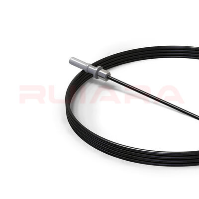
HFBR-4501 HFBR-4511 POF Cable Assembly

HFBR-4501 HFBR-4511 POF Cable Assembly

MOQ: 100
Price: USD 0.5–3.2/Piece
Delivery Period: 5-8 work days
Payment Method: L/C,D/A,D/P,T/T
Supply Capacity: 1W / Days
Detail Information
Product Type:
Finished Simplex POF Cable Assembly
Connector A:
HFBR-4501 Style, Gray
Connector B:
HFBR-4511 Style, Blue
Fiber Type:
1.0 Mm Step-index PMMA POF
Fiber Diameter:
Ø1.0 ±0.04 Mm
Standard Cable Jacket:
Black PE
Standard Cable OD:
Ø2.2 ±0.1 Mm
Optical Channels:
1
Existing Drawing Lengths:
1 M, 2 M, 3 M
1 M Drawing:
1000 ±10 Mm, Loss ≤2.0 DB
2 M Drawing:
2000 ±15 Mm, Loss ≤2.4 DB
3 M Drawing:
3000 ±15 Mm, Loss ≤2.8 DB
Drawing Test Condition:
650 Nm LED Related Condition
Boot Option:
40 Mm Black Boot Version Available
Dust Caps:
Available With Applicable Assembly Versions
Custom Length:
Available By Project Requirement
Custom Construction:
Jacket, Strain Relief, Protection Structure And Related Configuration Can Be Developed For Project Requirements
Product Description

Our HFBR-4501 HFBR-4511 POF cable assembly is a finished simplex plastic optical fiber cable for industrial control, power-system communication, equipment interconnection, and Broadcom/Avago Versatile Link–type optical interfaces.

The standard construction uses 1.0 mm PMMA plastic optical fiber, a black 2.2 mm PE jacket, a gray HFBR-4501-style connector on one end, and a blue HFBR-4511-style connector on the other. We manufacture the finished assembly through cable jacketing, cutting, connector termination, metal-ring crimping, fiber-end finishing, and final assembly.

This is a passive single-channel POF cable assembly. It does not determine system data rate or maximum communication distance by itself; those depend on the complete transmitter–fiber–receiver link.

HFBR-4501 and HFBR-4511 Interface Relationship

HFBR-4501 and HFBR-4511 belong to the Broadcom/Avago Versatile Link connector family. In the standard simplex system, the HFBR-4501 side is gray and the HFBR-4511 side is blue.

The two connectors use the same basic mechanical interface. The color difference is primarily used to identify the transmitter and receiver sides of the optical link. It does not mean that the plastic optical fiber itself is directional.

Broadcom currently uses the formal part numbers HFBR-4501Z and HFBR-4511Z, while HFBR-4501 and HFBR-4511 remain common in equipment manuals, legacy documentation, and market searches. Our finished cable assembly uses the corresponding interface form, but it should not be confused with a Broadcom original cable assembly.

Typical link position:

Optical Tx → gray HFBR-4501 → POF cable → blue HFBR-4511 → Optical Rx
Finished Cable Manufacturing, Not Connector Resale

The product supplied here is a completed cable assembly rather than a pair of connectors fitted to purchased finished cable.

Our manufacturing scope includes:

  • POF cable jacketing and cable construction

  • Cutting and length control

  • HFBR connector assembly

  • Metal crimp-ring installation

  • Optional boot and dust-cap assembly

  • Fiber-end trimming and finishing

  • Final assembly and inspection

This manufacturing scope allows the cable construction and finished assembly to be configured around actual equipment and project requirements instead of being limited to a single fixed off-the-shelf cable format.

Standard Lengths and Custom Cable Lengths

Existing product drawings cover 1 m, 2 m, and 3 m assemblies with defined length tolerances and complete-assembly loss requirements.

Other lengths can be manufactured for project requirements. For custom lengths, the assembly should be defined by more than the nominal meter value. Length tolerance, tip-to-tip definition, cable construction, and the applicable finished-assembly optical-loss requirement should be confirmed together.

The wider market for HFBR-4501 / HFBR-4511 assemblies includes short patch cords and lengths extending to tens of meters, so custom-length requests are common in this product category. The practical length for a specific system, however, must also fit the optical budget of the transmitter, receiver, wavelength, fiber attenuation, connector losses, temperature, and required data rate.

Optical Loss Must Be Read at the Correct Product Level

POF specifications often use several different loss values that should not be mixed.

Bare-fiber transmission loss, jacketed-cable attenuation, connector or adapter coupling loss, and complete cable-assembly insertion loss describe different objects.

For example, Mitsubishi SK-series bare POF, Mitsubishi jacketed POF cable, Broadcom POF cable, HFBR mating adapters, and our finished 1 m / 2 m / 3 m assemblies all use different loss definitions and test conditions.

For purchasing and system matching, the most relevant value is the specification applicable to the finished assembly being supplied, not a bare-fiber or third-party cable value copied into the cable assembly specification.

Industrial Installation and Mechanical Handling

Our HFBR POF jump-cable installation guidance specifies:

  • Minimum cable bending radius: 22 mm

  • Temporary pulling force during installation: ≤50 N

  • Long-term tensile load: ≤1 N

  • Keep optical end faces free from dust, oil, scratches, and contamination

  • Avoid excessive bending, repeated twisting, knotting, and forced unwinding

  • Confirm compatibility before exposing the cable to cleaners, oils, solvents, adhesives, plasticizers, or other chemicals

These conditions apply to the finished HFBR jump cable and should not be replaced by bending or tensile values taken from unrelated bare-fiber or third-party cable specifications.

Cable Construction for Industrial Environments

The standard documented construction is a 2.2 mm black PE-jacketed cable, but industrial projects may require different mechanical or environmental characteristics.

Depending on the project, the assembly can be developed around requirements such as:

The required temperature, flame performance, chemical resistance, and mechanical strength should be treated as a combination of fiber grade, jacket material, connector, cable structure, and finished-assembly validation.

For that reason, we do not automatically transfer a third-party cable or connector temperature, UL, flame, or mechanical rating to the complete assembly.

Versatile Link Applications in Industrial and Power Systems

HFBR-4501 / HFBR-4511 interfaces are used in industrial optical links where electrical isolation, immunity to electrical interference, and simple short-distance fiber interconnection are required.

Relevant applications include:

  • Factory automation

  • Industrial control and fieldbus systems

  • Power electronics control

  • High-voltage galvanic isolation

  • Substation protection and control communication

  • Industrial equipment interconnection

  • Board-to-board and rack-to-rack optical links

ABB documentation provides a concrete example: the REF542plus protection and control unit identifies an HFBR-4501 gray TX optical interface and an HFBR-4511 blue RX optical interface for SPABUS plastic-fiber communication. ABB SPACOM / SPA documentation also shows HFBR-4501/4511 connectors used in POF protection and control communication links.

These references confirm the interface application environment. Final compatibility with a particular device should still be checked against the equipment interface, required length, and system optical budget.

Standard Inspection and Project-Specific Validation

For the current finished assembly, quality control can be organized around the characteristics defined by the applicable product drawing, including:

  • Cable appearance and construction

  • Length and configuration

  • Connector and crimp assembly

  • Fiber end-face condition

  • Complete-assembly optical loss under the specified test condition

For OEM or project requirements, additional validation can be organized for items such as connector retention, cable tensile performance, material selection, temperature requirements, flame performance, or other environmental conditions.

Technical drawings, dimensional information, and installation guidance can also be provided according to the product configuration. Compliance documents and test reports should be matched to the actual BOM, material version, and project scope rather than assumed from third-party connector or cable certifications.

For HFBR-4501 / HFBR-4511 POF cable assemblies, custom lengths, industrial cable structures, OEM requirements, or equipment-specific configurations, send us your required length and application details for configuration and quotation.

Products
PRODUCTS DETAILS
HFBR-4501 HFBR-4511 POF Cable Assembly
MOQ: 100
Price: USD 0.5–3.2/Piece
Delivery Period: 5-8 work days
Payment Method: L/C,D/A,D/P,T/T
Supply Capacity: 1W / Days
Detail Information
Product Type:
Finished Simplex POF Cable Assembly
Connector A:
HFBR-4501 Style, Gray
Connector B:
HFBR-4511 Style, Blue
Fiber Type:
1.0 Mm Step-index PMMA POF
Fiber Diameter:
Ø1.0 ±0.04 Mm
Standard Cable Jacket:
Black PE
Standard Cable OD:
Ø2.2 ±0.1 Mm
Optical Channels:
1
Existing Drawing Lengths:
1 M, 2 M, 3 M
1 M Drawing:
1000 ±10 Mm, Loss ≤2.0 DB
2 M Drawing:
2000 ±15 Mm, Loss ≤2.4 DB
3 M Drawing:
3000 ±15 Mm, Loss ≤2.8 DB
Drawing Test Condition:
650 Nm LED Related Condition
Boot Option:
40 Mm Black Boot Version Available
Dust Caps:
Available With Applicable Assembly Versions
Custom Length:
Available By Project Requirement
Custom Construction:
Jacket, Strain Relief, Protection Structure And Related Configuration Can Be Developed For Project Requirements
Minimum Order Quantity:
100
Price:
USD 0.5–3.2/Piece
Delivery Time:
5-8 work days
Payment Terms:
L/C,D/A,D/P,T/T
Supply Ability:
1W / Days
Product Description

Our HFBR-4501 HFBR-4511 POF cable assembly is a finished simplex plastic optical fiber cable for industrial control, power-system communication, equipment interconnection, and Broadcom/Avago Versatile Link–type optical interfaces.

The standard construction uses 1.0 mm PMMA plastic optical fiber, a black 2.2 mm PE jacket, a gray HFBR-4501-style connector on one end, and a blue HFBR-4511-style connector on the other. We manufacture the finished assembly through cable jacketing, cutting, connector termination, metal-ring crimping, fiber-end finishing, and final assembly.

This is a passive single-channel POF cable assembly. It does not determine system data rate or maximum communication distance by itself; those depend on the complete transmitter–fiber–receiver link.

HFBR-4501 and HFBR-4511 Interface Relationship

HFBR-4501 and HFBR-4511 belong to the Broadcom/Avago Versatile Link connector family. In the standard simplex system, the HFBR-4501 side is gray and the HFBR-4511 side is blue.

The two connectors use the same basic mechanical interface. The color difference is primarily used to identify the transmitter and receiver sides of the optical link. It does not mean that the plastic optical fiber itself is directional.

Broadcom currently uses the formal part numbers HFBR-4501Z and HFBR-4511Z, while HFBR-4501 and HFBR-4511 remain common in equipment manuals, legacy documentation, and market searches. Our finished cable assembly uses the corresponding interface form, but it should not be confused with a Broadcom original cable assembly.

Typical link position:

Optical Tx → gray HFBR-4501 → POF cable → blue HFBR-4511 → Optical Rx
Finished Cable Manufacturing, Not Connector Resale

The product supplied here is a completed cable assembly rather than a pair of connectors fitted to purchased finished cable.

Our manufacturing scope includes:

  • POF cable jacketing and cable construction

  • Cutting and length control

  • HFBR connector assembly

  • Metal crimp-ring installation

  • Optional boot and dust-cap assembly

  • Fiber-end trimming and finishing

  • Final assembly and inspection

This manufacturing scope allows the cable construction and finished assembly to be configured around actual equipment and project requirements instead of being limited to a single fixed off-the-shelf cable format.

Standard Lengths and Custom Cable Lengths

Existing product drawings cover 1 m, 2 m, and 3 m assemblies with defined length tolerances and complete-assembly loss requirements.

Other lengths can be manufactured for project requirements. For custom lengths, the assembly should be defined by more than the nominal meter value. Length tolerance, tip-to-tip definition, cable construction, and the applicable finished-assembly optical-loss requirement should be confirmed together.

The wider market for HFBR-4501 / HFBR-4511 assemblies includes short patch cords and lengths extending to tens of meters, so custom-length requests are common in this product category. The practical length for a specific system, however, must also fit the optical budget of the transmitter, receiver, wavelength, fiber attenuation, connector losses, temperature, and required data rate.

Optical Loss Must Be Read at the Correct Product Level

POF specifications often use several different loss values that should not be mixed.

Bare-fiber transmission loss, jacketed-cable attenuation, connector or adapter coupling loss, and complete cable-assembly insertion loss describe different objects.

For example, Mitsubishi SK-series bare POF, Mitsubishi jacketed POF cable, Broadcom POF cable, HFBR mating adapters, and our finished 1 m / 2 m / 3 m assemblies all use different loss definitions and test conditions.

For purchasing and system matching, the most relevant value is the specification applicable to the finished assembly being supplied, not a bare-fiber or third-party cable value copied into the cable assembly specification.

Industrial Installation and Mechanical Handling

Our HFBR POF jump-cable installation guidance specifies:

  • Minimum cable bending radius: 22 mm

  • Temporary pulling force during installation: ≤50 N

  • Long-term tensile load: ≤1 N

  • Keep optical end faces free from dust, oil, scratches, and contamination

  • Avoid excessive bending, repeated twisting, knotting, and forced unwinding

  • Confirm compatibility before exposing the cable to cleaners, oils, solvents, adhesives, plasticizers, or other chemicals

These conditions apply to the finished HFBR jump cable and should not be replaced by bending or tensile values taken from unrelated bare-fiber or third-party cable specifications.

Cable Construction for Industrial Environments

The standard documented construction is a 2.2 mm black PE-jacketed cable, but industrial projects may require different mechanical or environmental characteristics.

Depending on the project, the assembly can be developed around requirements such as:

The required temperature, flame performance, chemical resistance, and mechanical strength should be treated as a combination of fiber grade, jacket material, connector, cable structure, and finished-assembly validation.

For that reason, we do not automatically transfer a third-party cable or connector temperature, UL, flame, or mechanical rating to the complete assembly.

Versatile Link Applications in Industrial and Power Systems

HFBR-4501 / HFBR-4511 interfaces are used in industrial optical links where electrical isolation, immunity to electrical interference, and simple short-distance fiber interconnection are required.

Relevant applications include:

  • Factory automation

  • Industrial control and fieldbus systems

  • Power electronics control

  • High-voltage galvanic isolation

  • Substation protection and control communication

  • Industrial equipment interconnection

  • Board-to-board and rack-to-rack optical links

ABB documentation provides a concrete example: the REF542plus protection and control unit identifies an HFBR-4501 gray TX optical interface and an HFBR-4511 blue RX optical interface for SPABUS plastic-fiber communication. ABB SPACOM / SPA documentation also shows HFBR-4501/4511 connectors used in POF protection and control communication links.

These references confirm the interface application environment. Final compatibility with a particular device should still be checked against the equipment interface, required length, and system optical budget.

Standard Inspection and Project-Specific Validation

For the current finished assembly, quality control can be organized around the characteristics defined by the applicable product drawing, including:

  • Cable appearance and construction

  • Length and configuration

  • Connector and crimp assembly

  • Fiber end-face condition

  • Complete-assembly optical loss under the specified test condition

For OEM or project requirements, additional validation can be organized for items such as connector retention, cable tensile performance, material selection, temperature requirements, flame performance, or other environmental conditions.

Technical drawings, dimensional information, and installation guidance can also be provided according to the product configuration. Compliance documents and test reports should be matched to the actual BOM, material version, and project scope rather than assumed from third-party connector or cable certifications.

For HFBR-4501 / HFBR-4511 POF cable assemblies, custom lengths, industrial cable structures, OEM requirements, or equipment-specific configurations, send us your required length and application details for configuration and quotation.