logo
Products
PRODUCTS DETAILS
Home > Products >
HFBR-4501Z to HFBR-4511Z POF Cable Assembly

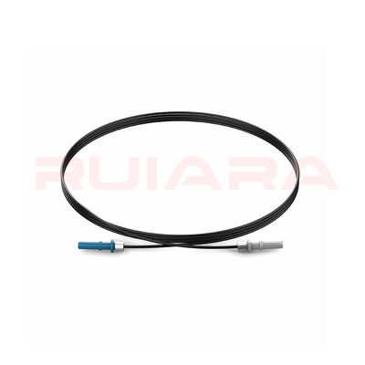
HFBR-4501Z to HFBR-4511Z POF Cable Assembly

MOQ: 10
Price: 1.3-3.6
Delivery Period: 3
Payment Method: L/C,D/A,T/T,D/P
Detail Information
Place of Origin
China
Brand Name
Ruiara
Model Number
HFBR-4501Z to HFBR-4511Z
Product Type:
Finished Industrial POF Cable Assembly
Optical Medium:
Approximately 1.0 Mm Mitsubishi Chemical POF; Current Material Information Indicates An SK-grade Fiber, With The Exact MPN Confirmed In The Order Specification
Channel Configuration:
Simplex, One Fiber And One Optical Channel
Connector Configuration:
HFBR‑4501Z Gray Connector To HFBR‑4511Z Blue Connector
Connector Style:
Non-latching, Crimp-termination Versatile Link Style
Connector Sourcing:
Traceable Original Broadcom Connectors Or Disclosed HFBR-compatible Connectors
Standard Connector-side Cable Diameter:
Nominal 2.2 Mm; Reference Interface Range 2.13–2.27 Mm
Main Cable Construction:
Standard 2.2 Mm, Double-jacket, Reinforced Or Custom 4–6 Mm Construction
Jacket Options:
PE, PVC, PUR, Nylon, CPE Or Project-specific Composite Construction
Reinforcement:
Optional Reinforcement And Strain-transfer Structure For Mechanically Demanding Installations
Length:
Common Or Custom Lengths, Defined Connector-end To Connector-end With Project-specific Tolerance
Termination:
Crimp Termination With Controlled Cutting, Grinding And Polishing
End Protection:
Optional Strain Relief, Heat-shrink Transition, Adhesive-assisted Termination Or Protective Boot
Jacket Identification:
Custom Color, Printing, Customer Part Number, Length And Batch Labeling
Inspection:
Configuration, Length, Appearance And End-face Inspection
Optical Testing:
End-to-end Insertion-loss Testing At An Agreed Wavelength And Reference Method
Project Testing:
Optional Connector Retention, Tensile, Bending, Temperature Or Environmental Verification
Compliance Support:
RoHS Material Configuration, UL-rated Cable Options, Halogen-free Cable Options, Material Declarations, COA And Batch Traceability Subject To The Selected BOM
Packaging:
Dust Caps, Individual Labels, Individual Bags Or Antistatic Packaging
Product Description

This HFBR-4501Z to HFBR-4511Z POF Cable Assembly is a finished, simplex industrial plastic optical fiber assembly for short-distance optical signal connections in the Broadcom/Avago Versatile Link ecosystem. It combines approximately 1.0 mm Mitsubishi Chemical POF with a gray transmit-side connector, a blue receive-side connector, protective cable construction, crimp termination and controlled end-face finishing.

We manufacture the jacketed cable structure and complete the connector termination in-house. Standard 2.2 mm assemblies, reinforced 4–6 mm constructions, custom lengths, original Broadcom connectors and interface-compatible connector options can be configured according to the equipment, environment and project requirements.

HFBR‑4501Z and HFBR‑4511Z are connector part numbers, not complete cable part numbers. The finished product supplied here includes the optical fiber, protective cable structure, crimp rings, connectors, processed fiber ends and agreed inspection.

HFBR-4501Z to HFBR-4511Z POF Cable Assembly

Gray and Blue Connector Identification

HFBR‑4501Z and HFBR‑4511Z have the same basic mechanical interface and fiber-size requirements:

  • HFBR‑4501Z is gray and is normally used to identify the transmitter side.

  • HFBR‑4511Z is blue and is normally used to identify the receiver side.

  • The color difference supports installation and port identification; it does not indicate different optical performance.

  • “Simplex” means one fiber and one channel. It does not mean single-mode fiber.

  • These are non-latching POF connectors retained by the snap-in or friction structure of a compatible Versatile Link port.

  • Their polished plastic-fiber end face is not an APC interface.

The complete “Z” suffix should be retained when identifying current RoHS-version connectors. Historical documents may use HFBR‑4501 or HFBR‑4511 without the suffix and may refer to HP or Avago instead of Broadcom.

Original and Compatible Connector Options

For projects requiring original connectors, we can organize the assembly with traceable Broadcom HFBR‑4501Z and HFBR‑4511Z parts and confirm the manufacturer and complete MPN in the BOM.

For cost-controlled or alternative-sourcing projects, HFBR-interface-compatible connectors can also be evaluated. Compatible parts are identified according to their actual source and are not represented as Broadcom-manufactured components. Mechanical fit, retention and optical performance can be included in the sample-validation plan.

Connector Interface Reference

The following values describe the standard connector interface and prescribed 2.2 mm termination conditions. They are useful for design review but do not automatically become guaranteed values for every custom finished assembly.

Reference Item Value or Condition
Compatible POF diameter Approximately 1.0 mm including optical cladding
Standard jacketed cable range 2.13–2.27 mm
Port retention at 25°C Minimum approximately 7 N; typical approximately 8 N
Port retention over the specified temperature range Minimum approximately 3 N
Connector-to-cable pull force Minimum approximately 8.5 N; typical approximately 22 N
Connector insertion force Approximately 8–30 N
Unstressed connector operating/storage reference −40 to +85°C
Installation, termination and mating temperature 0 to +70°C
Mated interface through HFBR‑4505Z/4515Z adapter Typical loss approximately 1.5 dB; maximum approximately 2.8 dB

Port retention, connector-to-cable pull force and insertion force are different measurements. For custom jacketed or reinforced assemblies, the required acceptance value should be defined and verified on the finished construction.

Cable Construction Designed Around the 2.2 mm Crimp Interface

The standard HFBR‑4501Z/4511Z crimp area is designed for an approximately 2.2 mm cable section. A standard 2.2 mm POF cable can therefore enter the crimp ring directly after controlled stripping and fiber preparation.

A 4–6 mm outer jacket cannot be inserted directly into the standard crimp ring. Reinforced assemblies require a transition that preserves an approximately 2.2 mm connector-side inner cable while transferring tensile and bending loads into the larger outer structure.

Construction Connector-End Design Typical Selection Logic
Standard 2.2 mm Direct crimp onto the controlled 2.2 mm jacket section Compact internal wiring and standard Versatile Link connections
Double-jacket 4 mm Approximately 2.2 mm inner cable with a larger protective outer jacket removed before the connector Additional mechanical protection while retaining the standard crimp interface
Reinforced 5–6 mm Inner POF cable, reinforcement, outer jacket and engineered strain-transfer transition Installations requiring greater tensile, abrasion or routing protection
High-temperature project construction Temperature-compatible POF grade, jacket, adhesive, heat-shrink and termination materials selected as one system Applications where changing only the jacket would not provide the required temperature performance

For large-diameter constructions, the design review defines the outer-jacket stripping length, exposed inner-cable length, reinforcement anchoring, heat-shrink or boot geometry, adhesive requirement and minimum bend space. Prototype optical, tensile, bending and retention checks are recommended before volume production.

POF Material, Attenuation and End-Face Control

The optical fiber contains a PMMA core and fluorinated-polymer optical cladding. “Bare POF” means that no protective cable jacket has been added; it does not mean that the PMMA core has no optical cladding.

When the ordered material is confirmed as Mitsubishi Chemical SK‑40, its reference construction is a step-index POF with:

  • Typical optical-core diameter of approximately 980 µm

  • Typical total diameter, including optical cladding, of approximately 1,000 µm

  • Numerical aperture of approximately 0.5

  • Maximum bare-fiber attenuation of 0.15 dB/m under a 650 nm, 25°C, collimated-light, 10 m-to-1 m cutback test

  • Minimum bend-radius reference of 25 mm

  • Tensile force of at least 65 N at 5% elongation

The complete fiber MPN is confirmed from the material label, purchasing record or COA when the project requires SK‑40-specific documentation.

Why Raw-Fiber and Finished-Cable Values Are Different
Reference Object Attenuation Reference Important Condition
SK‑40 bare POF Maximum 0.15 dB/m 650 nm, 25°C, collimated light, 10 m-to-1 m cutback
SH‑4001 2.2 mm PE-jacketed POF Maximum 0.19 dB/m at 25°C and 50% RH; up to 0.21 dB/m over its stated operating range Complete jacketed cable, not bare fiber
Broadcom R-grade reference cable Typical 0.22 dB/m; maximum 0.27 dB/m 660 nm HFBR LED, NA 0.5, 50 m
Broadcom E-grade reference cable Typical 0.19 dB/m; maximum 0.23 dB/m 660 nm HFBR LED, NA 0.5, 50 m

These values describe different fibers or cables under different test conditions. They cannot be directly subtracted to calculate a jacketing penalty, and none of them replaces finished-assembly testing.

Extrusion temperature, radial pressure, material shrinkage, eccentricity, residual stress, bending, termination and polishing can all affect final optical performance. Mechanical performance is likewise determined by the complete load path through the jacket, reinforcement, crimp ring, adhesive and strain-relief structure.

Controlled Termination and Polishing

A standard 2.2 mm crimp termination is controlled around several critical dimensions and process points:

  1. Remove approximately 7 mm of the protective jacket.

  2. Position the crimp ring before inserting the fiber.

  3. Allow the fiber to extend approximately 3 mm beyond the connector face.

  4. Complete the crimp with the ring correctly positioned in the crimp area.

  5. Trim the protruding fiber while leaving enough material for controlled grinding.

  6. Grind the end face flush and finish it with a fine polishing film.

  7. Inspect the end face for flatness, smoothness and contamination.

A 3 µm fine-polish step can improve coupling performance by approximately 2 dB compared with a coarse 600-grit-only finish under the referenced interface conditions. Adhesive-assisted termination, finer polishing or non-corrosive RTV can be evaluated for rugged or temperature-cycling projects, but the resulting assembly is qualified through its own test plan.

Finished-Assembly Loss and Test Definition

End-to-end assembly loss includes:

  • Attenuation through the actual cable length

  • Loss from both connector terminations

  • Loss from any inline adapter or additional mating interface

  • The effect of bending, temperature and the selected reference method

For this reason, a connector-interface value or raw-fiber attenuation cannot be presented as the loss of the complete assembly.

POF assembly insertion loss may be measured with a single-ended FOTP‑171-type arrangement or a double-ended OFSTP‑7/14-type arrangement. The report should identify the wavelength, light source, reference cable, adapter arrangement and reference method.

Reference normalization also changes what the reported result includes:

  • Method A normally retains the complete assembly insertion loss.

  • Method B removes one reference-connection loss.

  • Method C removes the effects assigned to two mating connections and the reference fiber.

Results obtained with different normalization methods should not be compared without reviewing the setup.

Depending on the project, the quality package can include:

  • BOM and configuration confirmation

  • Connector-end-to-connector-end length measurement

  • Appearance, dimensional and end-face inspection

  • End-to-end insertion-loss testing under an agreed method

  • Connector retention or cable pull testing

  • Bending, temperature or environmental verification

  • Individual test records, material documents and batch traceability

Only tests actually performed on the ordered assembly are reported as finished-product results.

Speed and Distance Depend on the Complete Versatile Link

HFBR‑4501Z and HFBR‑4511Z are passive connectors. They do not independently define the data rate or maximum transmission distance.

The usable link depends on the transmitter and receiver MPNs, optical wavelength, cable attenuation, assembly length, connector and adapter losses, operating temperature, receiver sensitivity, aging allowance and design margin.

Representative Versatile Link family examples include:

Transmitter / Receiver Pair Representative Rate Published Link Reference
HFBR‑1523Z / HFBR‑2523Z 40 kBd Up to approximately 111 m with the specified low-loss POF configuration
HFBR‑1522Z / HFBR‑2522Z 1 MBd Approximately 45 m in the referenced high-performance configuration
HFBR‑1521Z / HFBR‑2521Z 5 MBd Approximately 22 m
HFBR‑1528Z / HFBR‑2528Z 10 MBd Approximately 40 m at 0 to +70°C or 30 m at −20 to +85°C

Other specialized module combinations in the family cover rates up to approximately 155 MBd. These are module- and condition-specific references, not universal distance ratings for the cable assembly.

A preliminary maximum-length estimate can be expressed as:

Maximum length ≈ (minimum transmitter power − receiver sensitivity − connection losses − design margin) ÷ maximum cable attenuation

For a project calculation, provide the complete transmitter and receiver MPNs, operating temperature, target length, number of mating interfaces and required system margin.

Industrial Applications and Equipment Matching

This simplex Versatile Link POF cable assembly is relevant to short-distance optical control and signal-isolation links such as:

  • PLC and industrial computer communication

  • Robot and factory-control equipment

  • Industrial sensing and data acquisition

  • High-voltage sensing and galvanically isolated control

  • Wind and photovoltaic inverter control

  • IGBT gate-drive and SVC control links

  • Industrial network extensions

  • Equipment-internal optical signal connections

Equipment compatibility must be confirmed from the actual port, module and link conditions. As one documented equipment example, the ABB REF542plus SPABUS interface identifies X60 as a gray HFBR‑4501 transmit port and X61 as a blue HFBR‑4511 receive port, with a plastic-fiber length limit of 30 m in that equipment manual. This provides a useful identification reference but does not imply approval for every ABB model or equipment revision.

Related Versatile Link Connector Options
Related Part Main Difference
HFBR‑4503Z / HFBR‑4513Z Simplex crimp connectors with a latching structure
HFBR‑4506Z Duplex crimp connector without an independent latch
HFBR‑4516Z Duplex crimp connector with a latching structure
HFBR‑4531Z/4532Z/4533Z/4535Z series Crimpless termination alternatives
HFBR‑4505Z / HFBR‑4515Z Bulkhead feed-through adapters for mating terminated simplex connectors
HFBR‑4525Z Simplex crimp ring
HFBR‑4526Z Duplex crimp ring; not interchangeable with the simplex version
HFBR‑4522Z Versatile Link port dust plug

HFBR-4501Z to HFBR-4511Z POF Cable Assembly

These parts can be evaluated when a project requires a latch, duplex channel, crimpless installation, panel feed-through or related accessory supply. They are separate configurations rather than automatic substitutes for the HFBR‑4501Z/4511Z assembly.

Custom and OEM Project Support

As a custom industrial POF cable assembly manufacturer, we can support standard configurations, semi-custom assemblies and drawing- or sample-based OEM projects.

A typical project path includes:

  1. Review the existing cable, equipment port, drawing, sample or part number.

  2. Confirm the POF grade, connector source and simplex channel configuration.

  3. Review cable diameter, jacket material, reinforcement and connector transition for manufacturability.

  4. Produce a prototype or first article.

  5. Verify the agreed optical, dimensional and mechanical requirements.

  6. Move through pilot production to repeat batch production with inspection and traceability.

Available project options include custom jacket color and printing, customer part numbers, individual labels, dust caps, antistatic packaging, RoHS material configurations, UL-rated cable constructions, halogen-free cable options and supporting material documentation.

Using a UL-rated cable or a UL94 V‑0 connector does not by itself mean that the complete custom assembly holds an independent UL certification. Compliance is stated according to the actual component, material and finished-product documentation included in the approved BOM.

Send Your Required Configuration

Send the required length, quantity and original-or-compatible connector preference to start a configuration review. If the specification is not yet complete, send the equipment model, existing cable photo, drawing or sample information, and we can begin from there.

Products
PRODUCTS DETAILS
HFBR-4501Z to HFBR-4511Z POF Cable Assembly
MOQ: 10
Price: 1.3-3.6
Delivery Period: 3
Payment Method: L/C,D/A,T/T,D/P
Detail Information
Place of Origin
China
Brand Name
Ruiara
Model Number
HFBR-4501Z to HFBR-4511Z
Product Type:
Finished Industrial POF Cable Assembly
Optical Medium:
Approximately 1.0 Mm Mitsubishi Chemical POF; Current Material Information Indicates An SK-grade Fiber, With The Exact MPN Confirmed In The Order Specification
Channel Configuration:
Simplex, One Fiber And One Optical Channel
Connector Configuration:
HFBR‑4501Z Gray Connector To HFBR‑4511Z Blue Connector
Connector Style:
Non-latching, Crimp-termination Versatile Link Style
Connector Sourcing:
Traceable Original Broadcom Connectors Or Disclosed HFBR-compatible Connectors
Standard Connector-side Cable Diameter:
Nominal 2.2 Mm; Reference Interface Range 2.13–2.27 Mm
Main Cable Construction:
Standard 2.2 Mm, Double-jacket, Reinforced Or Custom 4–6 Mm Construction
Jacket Options:
PE, PVC, PUR, Nylon, CPE Or Project-specific Composite Construction
Reinforcement:
Optional Reinforcement And Strain-transfer Structure For Mechanically Demanding Installations
Length:
Common Or Custom Lengths, Defined Connector-end To Connector-end With Project-specific Tolerance
Termination:
Crimp Termination With Controlled Cutting, Grinding And Polishing
End Protection:
Optional Strain Relief, Heat-shrink Transition, Adhesive-assisted Termination Or Protective Boot
Jacket Identification:
Custom Color, Printing, Customer Part Number, Length And Batch Labeling
Inspection:
Configuration, Length, Appearance And End-face Inspection
Optical Testing:
End-to-end Insertion-loss Testing At An Agreed Wavelength And Reference Method
Project Testing:
Optional Connector Retention, Tensile, Bending, Temperature Or Environmental Verification
Compliance Support:
RoHS Material Configuration, UL-rated Cable Options, Halogen-free Cable Options, Material Declarations, COA And Batch Traceability Subject To The Selected BOM
Packaging:
Dust Caps, Individual Labels, Individual Bags Or Antistatic Packaging
Minimum Order Quantity:
10
Price:
1.3-3.6
Delivery Time:
3
Payment Terms:
L/C,D/A,T/T,D/P
Product Description

This HFBR-4501Z to HFBR-4511Z POF Cable Assembly is a finished, simplex industrial plastic optical fiber assembly for short-distance optical signal connections in the Broadcom/Avago Versatile Link ecosystem. It combines approximately 1.0 mm Mitsubishi Chemical POF with a gray transmit-side connector, a blue receive-side connector, protective cable construction, crimp termination and controlled end-face finishing.

We manufacture the jacketed cable structure and complete the connector termination in-house. Standard 2.2 mm assemblies, reinforced 4–6 mm constructions, custom lengths, original Broadcom connectors and interface-compatible connector options can be configured according to the equipment, environment and project requirements.

HFBR‑4501Z and HFBR‑4511Z are connector part numbers, not complete cable part numbers. The finished product supplied here includes the optical fiber, protective cable structure, crimp rings, connectors, processed fiber ends and agreed inspection.

HFBR-4501Z to HFBR-4511Z POF Cable Assembly

Gray and Blue Connector Identification

HFBR‑4501Z and HFBR‑4511Z have the same basic mechanical interface and fiber-size requirements:

  • HFBR‑4501Z is gray and is normally used to identify the transmitter side.

  • HFBR‑4511Z is blue and is normally used to identify the receiver side.

  • The color difference supports installation and port identification; it does not indicate different optical performance.

  • “Simplex” means one fiber and one channel. It does not mean single-mode fiber.

  • These are non-latching POF connectors retained by the snap-in or friction structure of a compatible Versatile Link port.

  • Their polished plastic-fiber end face is not an APC interface.

The complete “Z” suffix should be retained when identifying current RoHS-version connectors. Historical documents may use HFBR‑4501 or HFBR‑4511 without the suffix and may refer to HP or Avago instead of Broadcom.

Original and Compatible Connector Options

For projects requiring original connectors, we can organize the assembly with traceable Broadcom HFBR‑4501Z and HFBR‑4511Z parts and confirm the manufacturer and complete MPN in the BOM.

For cost-controlled or alternative-sourcing projects, HFBR-interface-compatible connectors can also be evaluated. Compatible parts are identified according to their actual source and are not represented as Broadcom-manufactured components. Mechanical fit, retention and optical performance can be included in the sample-validation plan.

Connector Interface Reference

The following values describe the standard connector interface and prescribed 2.2 mm termination conditions. They are useful for design review but do not automatically become guaranteed values for every custom finished assembly.

Reference Item Value or Condition
Compatible POF diameter Approximately 1.0 mm including optical cladding
Standard jacketed cable range 2.13–2.27 mm
Port retention at 25°C Minimum approximately 7 N; typical approximately 8 N
Port retention over the specified temperature range Minimum approximately 3 N
Connector-to-cable pull force Minimum approximately 8.5 N; typical approximately 22 N
Connector insertion force Approximately 8–30 N
Unstressed connector operating/storage reference −40 to +85°C
Installation, termination and mating temperature 0 to +70°C
Mated interface through HFBR‑4505Z/4515Z adapter Typical loss approximately 1.5 dB; maximum approximately 2.8 dB

Port retention, connector-to-cable pull force and insertion force are different measurements. For custom jacketed or reinforced assemblies, the required acceptance value should be defined and verified on the finished construction.

Cable Construction Designed Around the 2.2 mm Crimp Interface

The standard HFBR‑4501Z/4511Z crimp area is designed for an approximately 2.2 mm cable section. A standard 2.2 mm POF cable can therefore enter the crimp ring directly after controlled stripping and fiber preparation.

A 4–6 mm outer jacket cannot be inserted directly into the standard crimp ring. Reinforced assemblies require a transition that preserves an approximately 2.2 mm connector-side inner cable while transferring tensile and bending loads into the larger outer structure.

Construction Connector-End Design Typical Selection Logic
Standard 2.2 mm Direct crimp onto the controlled 2.2 mm jacket section Compact internal wiring and standard Versatile Link connections
Double-jacket 4 mm Approximately 2.2 mm inner cable with a larger protective outer jacket removed before the connector Additional mechanical protection while retaining the standard crimp interface
Reinforced 5–6 mm Inner POF cable, reinforcement, outer jacket and engineered strain-transfer transition Installations requiring greater tensile, abrasion or routing protection
High-temperature project construction Temperature-compatible POF grade, jacket, adhesive, heat-shrink and termination materials selected as one system Applications where changing only the jacket would not provide the required temperature performance

For large-diameter constructions, the design review defines the outer-jacket stripping length, exposed inner-cable length, reinforcement anchoring, heat-shrink or boot geometry, adhesive requirement and minimum bend space. Prototype optical, tensile, bending and retention checks are recommended before volume production.

POF Material, Attenuation and End-Face Control

The optical fiber contains a PMMA core and fluorinated-polymer optical cladding. “Bare POF” means that no protective cable jacket has been added; it does not mean that the PMMA core has no optical cladding.

When the ordered material is confirmed as Mitsubishi Chemical SK‑40, its reference construction is a step-index POF with:

  • Typical optical-core diameter of approximately 980 µm

  • Typical total diameter, including optical cladding, of approximately 1,000 µm

  • Numerical aperture of approximately 0.5

  • Maximum bare-fiber attenuation of 0.15 dB/m under a 650 nm, 25°C, collimated-light, 10 m-to-1 m cutback test

  • Minimum bend-radius reference of 25 mm

  • Tensile force of at least 65 N at 5% elongation

The complete fiber MPN is confirmed from the material label, purchasing record or COA when the project requires SK‑40-specific documentation.

Why Raw-Fiber and Finished-Cable Values Are Different
Reference Object Attenuation Reference Important Condition
SK‑40 bare POF Maximum 0.15 dB/m 650 nm, 25°C, collimated light, 10 m-to-1 m cutback
SH‑4001 2.2 mm PE-jacketed POF Maximum 0.19 dB/m at 25°C and 50% RH; up to 0.21 dB/m over its stated operating range Complete jacketed cable, not bare fiber
Broadcom R-grade reference cable Typical 0.22 dB/m; maximum 0.27 dB/m 660 nm HFBR LED, NA 0.5, 50 m
Broadcom E-grade reference cable Typical 0.19 dB/m; maximum 0.23 dB/m 660 nm HFBR LED, NA 0.5, 50 m

These values describe different fibers or cables under different test conditions. They cannot be directly subtracted to calculate a jacketing penalty, and none of them replaces finished-assembly testing.

Extrusion temperature, radial pressure, material shrinkage, eccentricity, residual stress, bending, termination and polishing can all affect final optical performance. Mechanical performance is likewise determined by the complete load path through the jacket, reinforcement, crimp ring, adhesive and strain-relief structure.

Controlled Termination and Polishing

A standard 2.2 mm crimp termination is controlled around several critical dimensions and process points:

  1. Remove approximately 7 mm of the protective jacket.

  2. Position the crimp ring before inserting the fiber.

  3. Allow the fiber to extend approximately 3 mm beyond the connector face.

  4. Complete the crimp with the ring correctly positioned in the crimp area.

  5. Trim the protruding fiber while leaving enough material for controlled grinding.

  6. Grind the end face flush and finish it with a fine polishing film.

  7. Inspect the end face for flatness, smoothness and contamination.

A 3 µm fine-polish step can improve coupling performance by approximately 2 dB compared with a coarse 600-grit-only finish under the referenced interface conditions. Adhesive-assisted termination, finer polishing or non-corrosive RTV can be evaluated for rugged or temperature-cycling projects, but the resulting assembly is qualified through its own test plan.

Finished-Assembly Loss and Test Definition

End-to-end assembly loss includes:

  • Attenuation through the actual cable length

  • Loss from both connector terminations

  • Loss from any inline adapter or additional mating interface

  • The effect of bending, temperature and the selected reference method

For this reason, a connector-interface value or raw-fiber attenuation cannot be presented as the loss of the complete assembly.

POF assembly insertion loss may be measured with a single-ended FOTP‑171-type arrangement or a double-ended OFSTP‑7/14-type arrangement. The report should identify the wavelength, light source, reference cable, adapter arrangement and reference method.

Reference normalization also changes what the reported result includes:

  • Method A normally retains the complete assembly insertion loss.

  • Method B removes one reference-connection loss.

  • Method C removes the effects assigned to two mating connections and the reference fiber.

Results obtained with different normalization methods should not be compared without reviewing the setup.

Depending on the project, the quality package can include:

  • BOM and configuration confirmation

  • Connector-end-to-connector-end length measurement

  • Appearance, dimensional and end-face inspection

  • End-to-end insertion-loss testing under an agreed method

  • Connector retention or cable pull testing

  • Bending, temperature or environmental verification

  • Individual test records, material documents and batch traceability

Only tests actually performed on the ordered assembly are reported as finished-product results.

Speed and Distance Depend on the Complete Versatile Link

HFBR‑4501Z and HFBR‑4511Z are passive connectors. They do not independently define the data rate or maximum transmission distance.

The usable link depends on the transmitter and receiver MPNs, optical wavelength, cable attenuation, assembly length, connector and adapter losses, operating temperature, receiver sensitivity, aging allowance and design margin.

Representative Versatile Link family examples include:

Transmitter / Receiver Pair Representative Rate Published Link Reference
HFBR‑1523Z / HFBR‑2523Z 40 kBd Up to approximately 111 m with the specified low-loss POF configuration
HFBR‑1522Z / HFBR‑2522Z 1 MBd Approximately 45 m in the referenced high-performance configuration
HFBR‑1521Z / HFBR‑2521Z 5 MBd Approximately 22 m
HFBR‑1528Z / HFBR‑2528Z 10 MBd Approximately 40 m at 0 to +70°C or 30 m at −20 to +85°C

Other specialized module combinations in the family cover rates up to approximately 155 MBd. These are module- and condition-specific references, not universal distance ratings for the cable assembly.

A preliminary maximum-length estimate can be expressed as:

Maximum length ≈ (minimum transmitter power − receiver sensitivity − connection losses − design margin) ÷ maximum cable attenuation

For a project calculation, provide the complete transmitter and receiver MPNs, operating temperature, target length, number of mating interfaces and required system margin.

Industrial Applications and Equipment Matching

This simplex Versatile Link POF cable assembly is relevant to short-distance optical control and signal-isolation links such as:

  • PLC and industrial computer communication

  • Robot and factory-control equipment

  • Industrial sensing and data acquisition

  • High-voltage sensing and galvanically isolated control

  • Wind and photovoltaic inverter control

  • IGBT gate-drive and SVC control links

  • Industrial network extensions

  • Equipment-internal optical signal connections

Equipment compatibility must be confirmed from the actual port, module and link conditions. As one documented equipment example, the ABB REF542plus SPABUS interface identifies X60 as a gray HFBR‑4501 transmit port and X61 as a blue HFBR‑4511 receive port, with a plastic-fiber length limit of 30 m in that equipment manual. This provides a useful identification reference but does not imply approval for every ABB model or equipment revision.

Related Versatile Link Connector Options
Related Part Main Difference
HFBR‑4503Z / HFBR‑4513Z Simplex crimp connectors with a latching structure
HFBR‑4506Z Duplex crimp connector without an independent latch
HFBR‑4516Z Duplex crimp connector with a latching structure
HFBR‑4531Z/4532Z/4533Z/4535Z series Crimpless termination alternatives
HFBR‑4505Z / HFBR‑4515Z Bulkhead feed-through adapters for mating terminated simplex connectors
HFBR‑4525Z Simplex crimp ring
HFBR‑4526Z Duplex crimp ring; not interchangeable with the simplex version
HFBR‑4522Z Versatile Link port dust plug

HFBR-4501Z to HFBR-4511Z POF Cable Assembly

These parts can be evaluated when a project requires a latch, duplex channel, crimpless installation, panel feed-through or related accessory supply. They are separate configurations rather than automatic substitutes for the HFBR‑4501Z/4511Z assembly.

Custom and OEM Project Support

As a custom industrial POF cable assembly manufacturer, we can support standard configurations, semi-custom assemblies and drawing- or sample-based OEM projects.

A typical project path includes:

  1. Review the existing cable, equipment port, drawing, sample or part number.

  2. Confirm the POF grade, connector source and simplex channel configuration.

  3. Review cable diameter, jacket material, reinforcement and connector transition for manufacturability.

  4. Produce a prototype or first article.

  5. Verify the agreed optical, dimensional and mechanical requirements.

  6. Move through pilot production to repeat batch production with inspection and traceability.

Available project options include custom jacket color and printing, customer part numbers, individual labels, dust caps, antistatic packaging, RoHS material configurations, UL-rated cable constructions, halogen-free cable options and supporting material documentation.

Using a UL-rated cable or a UL94 V‑0 connector does not by itself mean that the complete custom assembly holds an independent UL certification. Compliance is stated according to the actual component, material and finished-product documentation included in the approved BOM.

Send Your Required Configuration

Send the required length, quantity and original-or-compatible connector preference to start a configuration review. If the specification is not yet complete, send the equipment model, existing cable photo, drawing or sample information, and we can begin from there.